


Gas porosity is the most common internal defect in aluminium die casting. It shows up as round, smooth cavities on X-ray. It causes leaks in structural parts. It ruins machined surfaces. And it costs foundries millions in scrap every year.
In my 25 years, I have traced gas porosity to two sources: hydrogen dissolved in the melt and air entrapped during filling. They look similar on a radiograph. They have different causes and different fixes.
Here is how I reduce both.
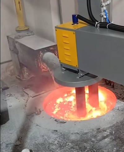
Degassing
The Two Sources of Gas Porosity
Hydrogen porosity comes from moisture. Every time aluminium meets water vapour, it absorbs hydrogen. The hydrogen stays dissolved in the liquid metal. During solidification, the solubility drops sharply. The hydrogen has to go somewhere. It forms bubbles. Those bubbles become porosity.
Air entrapment comes from turbulence. When metal fills the die cavity at high speed, it splashes and folds over itself. Air gets trapped. The vacuum system cannot remove it if the filling is too turbulent. Those air pockets become porosity.
The remedies are different. Hydrogen porosity is solved in the furnace. Air entrapment is solved in the die and the shot profile. Most foundries need to address both.
Step 1: Control Hydrogen in the Melt
Hydrogen is the enemy. You cannot see it. You cannot smell it. But you can measure it. And if you cannot measure it, you cannot control it.
I use a portable hydrogen analyser. I take a sample from the holding furnace before every shift. The target for structural die casting is below 0.15 ml/100g Al. For general commercial castings, below 0.25 ml/100g is acceptable.
If hydrogen is above target, the melt needs degassing.
Rotary Degassing
Manual lance degassing is inconsistent. The operator inserts a lance for three minutes, moves to the next ladle, and hopes for the best. There is no control. No measurement. No repeatability.
Rotary degassing changes that. A graphite rotor spins at 400–750 rpm. Argon or nitrogen is injected through the rotor and dispersed into fine bubbles. The bubbles rise through the melt, absorbing hydrogen as they go.
The key parameters I use:
| Parameter | Recommended Range |
|---|---|
| Rotor speed | 400–750 rpm |
| Gas flow rate | 15–25 L/min |
| Degassing time | 5–10 minutes per batch |
| Gas type | Argon (better for reactive alloys) or nitrogen |
A study on rotary degassing-ultrasonic methods found that combining rotary degassing with ultrasonic treatment reduced degassing time by one third compared to rotary impeller alone, and increased gas removal by 20%. Inclusions were reduced by 3–6 times.
Ultrasonic treatment is not yet standard in most foundries. But rotary degassing alone, done properly, will get you to 0.15 ml/100g. That is enough for most structural parts.
Cover Flux and Flux Injection
A cover flux creates a barrier between the melt and the atmosphere. It slows hydrogen pickup during holding. For die casting, a chloride-based flux works well. Sprinkle a thin layer on the surface. It melts and forms a protective layer.
Flux injection goes further. A lance injects flux powder into the melt with a carrier gas. The flux reacts with oxides and helps float them to the surface. It also helps remove hydrogen. I use flux injection when hydrogen is persistently high and rotary degassing alone is not enough.
Step 2: Reduce Air Entrapment
Even with a clean melt, you can still get porosity from air entrapment. The die filling must be controlled.
Vacuum-Assisted Die Casting
The single most effective tool for reducing air entrapment is vacuum. Research using water analog experiments and flow simulations confirmed that vacuum application reduces the quantity of entrapped air and porosity in die cast samples. Samples cast with a strong vacuum — below 100 mbar — exhibited greater density and enhanced mechanical properties compared to those cast with a weaker vacuum or none at all.
A study on vacuum die casting of an Al-Si-Mn-Mg alloy found that increasing the vacuum level reduced both the equivalent diameter and the number of gas pores. It also facilitated a morphological change from shrinkage pores to gas-shrinkage pores, which are less detrimental to mechanical properties.
I recommend vacuum levels below 100 mbar for structural parts. For general commercial castings, below 200 mbar is adequate.
Shot Profile and Fast Shot Speed
The fast shot speed determines how quickly the metal fills the cavity. Too slow, and the metal freezes before filling. Too fast, and the flow becomes turbulent, creating air entrapment.
Research on process parameters found that increasing the fast shot speed reduced the equivalent diameter and number of shrinkage and gas-shrinkage pores, while also reducing gas pore quantity.
But there is a limit. Past a certain speed, the flow becomes chaotic. The metal splashes. Air is trapped regardless of vacuum. I tune the fast shot speed on every die. Start conservative, then increase until you see the first sign of turbulence on the surface. Back off by 10%.
Die Venting
Vacuum cannot remove air that has nowhere to go. The die must have adequate vents and overflows. I have written about die venting for EV parts before. The principles apply to any die casting.
Add exhaust grooves at the last points to fill. Increase overflow capacity. Keep vents clean. A blocked vent is as bad as no vent.
Step 3: Control Melt Temperature
Temperature affects both hydrogen solubility and fluidity. Higher temperature means more hydrogen absorption. Lower temperature means poorer fill.
For A380, I hold the furnace at 680–700°C. For ADC12, 660–680°C. These are starting points. Adjust based on wall thickness and part geometry.
I have written a detailed guide on optimising die casting furnace temperature for A380 and ADC12. The temperature you set in the holding furnace is not the temperature at the shot sleeve. Measure at the sleeve. If it is below 650°C, you will have cold shuts and poor feeding. If it is above 720°C, you will have gas porosity.
Step 4: Keep the Charge Clean
Hydrogen comes from moisture. Moisture comes from wet scrap, oily scrap, and coated scrap. A study on die casting conditions found that using excessive mold wash increased hydrogen and gas porosity. Blowing off the excess lubricant prevented hydrogen absorption and porosity formation.
The same principle applies to the charge. Pre-dry all scrap. Remove oil and coatings where possible. Store scrap under cover. If you charge wet scrap, you are adding hydrogen directly into the melt.
A Real Case from Guangdong
In 2024, I worked with a die casting plant in Guangdong that supplies motor housings to an EV OEM. Their leak test rejection rate was 9%. The defects were gas porosity.
We measured hydrogen in the holding furnace. It was 0.31 ml/100g Al. The target was 0.15.
The plant was using manual lance degassing. No measurement. No control.
We installed a rotary degasser with argon. We set the parameters: 650 rpm, 20 L/min argon, 8 minutes per 500 kg batch. We trained the operators to measure hydrogen before every pour.
We also checked the vacuum system. The vacuum level was 180 mbar. We found a leaking door seal on the die casting machine. We replaced it. Vacuum dropped to 85 mbar.
We increased the fast shot speed by 8% and adjusted the switch point.
Results after one month:
| Metric | Before | After |
|---|---|---|
| Hydrogen content | 0.31 ml/100g | 0.12 ml/100g |
| Vacuum level | 180 mbar | 85 mbar |
| Leak test rejection | 9.0% | 1.8% |
The annual saving was over $210,000. The investment was $11,500. Payback was under three weeks.
A Simple Checklist to Reduce Gas Porosity
Measure hydrogen. Target below 0.15 ml/100g for structural parts.
Use rotary degassing. Manual lance degassing is not consistent enough.
Measure before every pour. Adjust degassing time based on the reading.
Apply vacuum. Target below 100 mbar for structural parts.
Check vacuum seals. A leaking seal ruins the vacuum.
Tune the fast shot speed. Too slow is bad. Too fast is worse.
Maintain die vents and overflows. Clean them weekly.
Pre-dry scrap. Never charge wet material.
Control melt temperature. Measure at the shot sleeve, not the furnace.
Record everything. You cannot improve what you do not measure.
Final Thoughts
Gas porosity is not a mystery. It comes from hydrogen or air. Hydrogen is controlled in the furnace. Air is controlled in the die and the shot profile.
In my 25 years, I have seen foundries cut gas porosity rejection rates from double digits to under 2% without changing the die or the alloy. They changed the melt treatment and the vacuum. That is where the money is.
If you are fighting gas porosity, start by measuring hydrogen. If it is above 0.15, fix the degassing. Then check the vacuum. Then look at the shot profile. You will find the cause.
Internal links: Case Study – Reducing Die Casting Porosity at a Guangdong Automotive Foundry, How to Optimize Die Casting Furnace Temperature for A380 and ADC12 Alloys
About the Author: Hu Shenyue is a veteran aluminium melting furnace expert with 25 years of hands-on experience in China, Southeast Asia, India, the UK, and Europe. He writes practical, experience-based content on furnace selection, maintenance, and optimisation at SmeltPro.